


- How plastic extrusion machines work and why predictive maintenance is crucial
- Single screw extruders: screw geometry, L/D ratio and continuous plasticization control
- Thermal zoning of the barrel in extruders: heat management, sensors and hidden faults
- Co-rotating twin-screw extruders: modular elements, glass fiber wear and process control
- Counter-rotating twin-screw pumps for PVC: technological advantages, corrosion and maintenance issues
- Extruder barrel and cooling systems: how to avoid overheating and melt degradation
- Extrusion heads and dies: wear, proper cleaning and impact on product quality
- Calibrators, cooling tanks and haul-offs: the downstream components that determine dimensional stability
- Degassing in extruders: vacuum pumps, vent flooding and maintenance of venting systems
- Extruder diagnostics: pressure, temperature, motor current and vibrations as early signs of degradation
Technical guide to plastic extrusion machinery: single-screw and twin-screw extruders, barrels, dies, degassing, downstream lines, wear signals and maintenance strategies
Author: Marco Arezio. Expert in circular economy, polymer recycling and industrial plastic processing.
Maintenance Manual. Chapter 2: Plastic Extrusion Machinery
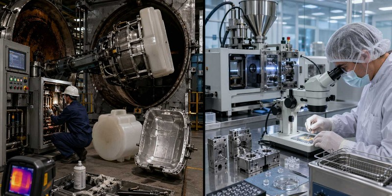
Extrusion is, among plastic processing methods, the one that more than any other has shaped continuous industrial production. Water pipes, building profiles, packaging films, electrical cables, sheets intended for thermoforming, boards, geomembranes, filaments, fibers: an enormous part of the industrial plastics world is born from a machine that does not operate in cycles, but in continuity. And it is precisely this continuity that constitutes the first technical and maintenance key to understanding the extruder.
Unlike the injection molding machine, which by its nature alternates phases of plasticizing, injection, cooling and mold reopening, the extruder is a machine that must maintain its balance for hours or even days, often without interruption. This means that degradation phenomena almost never appear suddenly. More frequently, they emerge as a slow process drift: a less stable throughput, a melt temperature moving away from its historical value, an increase in electrical absorption, a head pressure that no longer matches the baseline, a surface quality of the product that gradually worsens. In other words, the extruder “speaks” before it breaks down, but it does so through weak and progressive signals that only a well-structured predictive maintenance system is able to read.
In an extrusion plant, the quality of the finished product does not depend only on the quality of the raw material or on the precision of the thermal recipe. It depends on the actual condition of the screw, the barrel, the gearbox, the head, the cooling systems, the haul-offs, the vacuum pumps and all those subsystems that take part in the continuous process. For this reason, talking about extruders means speaking simultaneously about rheology, mechanics, heat transfer, tribology, construction materials and maintenance organization.
2.1 — Single-screw extruders: principle, thermal zoning and screw profiles
The single-screw extruder remains, even today, the most widespread machine in the plastics processing industry. Its success derives from a rare balance: structural simplicity, robustness, reliability, relatively contained costs and remarkable adaptability to the main commodity thermoplastics. Polyethylene, polypropylene, polystyrene, some engineering plastics, numerous compounds and many recycled formulations find in the single-screw extruder an adequate solution, provided that the screw has been designed consistently with the material and with the product to be manufactured.
The operating principle is well known but deserves to be recalled because almost all maintenance issues derive from it. The material in pellet or powder form enters through the hopper, is dragged by screw rotation inside the heated barrel, undergoes compaction, melting and homogenization, and is finally pushed toward the extrusion head. The melting process is not due only to the external heating generated by the thermal zones of the barrel: a relevant share of the energy derives from mechanical friction and viscous deformation of the polymer. It follows that the screw is not a mere conveying element, but the true energetic and rheological heart of the system.
In the single-screw extruder, continuity of flow is the fundamental goal. Any temperature inhomogeneity, any variation in channel filling degree, any alteration of screw or barrel geometry produces oscillations in pressure and throughput that are immediately reflected in the extruded product. Maintenance, therefore, must not be conceived as a response to failure, but as a discipline aimed at controlling process stability.
2.1.1 — Geometric parameters of the single screw
The single screw is an apparently simple geometry, but in reality every detail affects the material’s conveying, melting, pressurization and homogenization capacity. The first parameter to be considered is the diameter, indicated as D, which defines the machine’s size class. In laboratory micro-extruders or machines dedicated to special products, one may start from 18 or 25 mm, whereas in large lines for large-diameter pipes, high-voltage cables or sheets, one may reach 200 or 250 mm. This figure is not just a geometric measurement: it determines component size, spare-part costs, screw weight, disassembly complexity and maintenance logistics.
Alongside the diameter, the L/D ratio, that is, the ratio between the effective screw length and the diameter, is probably the most important parameter for understanding the function of an extrusion screw. In standard machines, the typical range lies between 24:1 and 34:1, but in high-performance configurations it may even reach 40:1. A high L/D ratio offers more space to melt, mix and stabilize the melt, but it also extends the internal surface subject to wear and increases the number of thermal zones to be controlled. In maintenance terms, this means more chances of drift, more critical points and greater attention to the consistency of the thermal profile along the machine.
The screw pitch, often equal to the diameter in the case of standard square-pitch screws, can become variable in special geometries. When the pitch changes along the screw length, the conveying and compression behavior of the material changes significantly, but maintenance complexity also increases, because each section becomes more sensitive to local wear and more difficult to assess using uniform criteria.
Also highly relevant is the compression ratio, generally between 2.0:1 and 4.5:1 depending on the material. High values allow strong compaction and good elimination of trapped air, but they increase mechanical stresses in the transition zone. This is a crucial aspect with recycled materials, especially when they vary in bulk density, moisture content or contamination level. Under such conditions, a screw that is too “aggressive” may produce torque peaks, local overheating and accelerated wear.
The channel depth in the metering zone, often between 0.05D and 0.07D, is the area where the melt is stabilized and pressure is built most effectively. Precisely for this reason it is also one of the areas where wear is most critical, especially with abrasive or filled materials. When the actual channel depth increases due to flight wear, the ability to build pressure decreases, the flow becomes less uniform and the process loses precision. For the same reason, the flight width, typically between 0.08D and 0.12D, must also be monitored: flank wear compromises the seal between screw and barrel and reduces pressurization efficiency.
In a well-organized maintenance program, geometric measurement of the screw cannot be limited to a generic visual inspection. High-risk zones must be identified, especially the transition and metering sections, and measured with suitable instruments, building up a wear history over time. It is only through this historical tracking that maintenance moves from intuitive to predictive.
2.1.2 — Thermal zoning of the barrel: management and critical issues
The barrel of a single-screw extruder is not a uniformly heated body, but a thermally articulated structure. A 90 mm extruder with an L/D ratio of 30:1, for example, is normally divided into 5, 6 or 7 independent heating zones, each equipped with band heaters or sector heaters and with its own control sensor, often thermocouples or PT100s. This means that the machine operates according to a true longitudinal thermal profile, which must be designed and maintained precisely.
The position along the screw at which the material completes melting, the overall energy level of the melt, its outlet viscosity and the pressure generated at the head depend largely on this profile. It is therefore not surprising that many production anomalies hastily attributed to raw material quality actually derive from a thermal zone that is no longer working as it should.
A degrading band heater rarely stops working suddenly. More often, in the initial phase, it takes longer to bring the zone to setpoint; subsequently it struggles to maintain temperature under load; finally, it goes into alarm or fails completely. This progression makes periodic verification of heaters and sensors one of the most profitable preventive activities in the entire extrusion machine park. It is not enough to read on the panel that the temperature “is fine”: the actual deviation between setpoint and effective temperature, the response speed, the continuity of control and, when necessary, the ohmic resistance of the heating elements must all be verified.
In extruders there is also a less evident but very dangerous critical issue: overheating of the melt due to excess mechanical energy. At high screw speeds, with viscous polymers or poorly optimized thermal profiles, the heat generated by friction can exceed the energy that the system is able to dissipate. In these cases, one is not facing a “lack of heating,” but rather an excess of internal energy. Thermal degradation may appear downstream, near the head, without the thermal picture of the barrel showing obvious anomalies. This is why monitoring the bulk melt temperature, carried out with immersion probes, represents a highly valuable diagnostic safeguard.
2.2 — Twin-screw extruders: co-rotating and counter-rotating
If the single-screw extruder is the machine of robustness and industrial diffusion, the twin-screw extruder is the machine of rheological precision and process flexibility. The presence of two coaxial screws housed in a figure-eight barrel profile makes it possible to handle the material in a far more sophisticated way. Distributive and dispersive mixing are superior, residence times are more controllable, devolatilization is more effective and the modularity of screw configuration makes it possible to adapt the machine to very different formulations.
For this reason, the twin-screw extruder is the reference platform for compounding, for processing filled materials, for handling complex formulations, for engineering polymers, for PVC and for numerous processes in which it is not enough simply to melt the material, but it is also necessary to disperse additives, break down agglomerates, mix fibers or evacuate volatiles. Naturally, an increase in performance corresponds to an increase in mechanical and maintenance complexity.
2.2.1 — Co-rotating twin screw: principle, screw elements and applications
In the co-rotating twin-screw extruder the two screws rotate in the same direction and are intermeshing. This condition generates the well-known self-wiping effect: material that tends to adhere to one screw is continuously “scraped” off by the other. The advantage is twofold. On the one hand, dead zones in which the polymer can stagnate and degrade are reduced; on the other, a more uniform distribution of residence times is achieved. For sensitive materials or for compounding processes, this aspect is decisive.
The internal geometry of the screws is not monolithic but modular. Conveying elements, kneading blocks and, when necessary, reverse elements are mounted on a supporting shaft. Conveying elements advance the material; kneading blocks, made up of angularly staggered discs, provide shear energy and mixing; reverse-thread elements slow down or oppose the flow, generating pressure and intensifying dispersive action. The sequence of these elements constitutes a true process architecture and represents a body of know-how often more important than the machine itself.
From a maintenance point of view, the screw elements of the co-rotating twin-screw extruder are particularly vulnerable when filled materials are processed. Formulations with 30% short glass fiber, such as certain PA6, PP or PBT bases, may generate in the most stressed zones, especially in melting and in the first kneading section, an average wear between 0.05 and 0.15 mm every 1,000 operating hours. When the filler is talc at 40 or 50% on a polypropylene matrix, wear tends to be significantly lower, often by 30–50% compared with glass-fiber compounds. In the case of fine calcium carbonate, especially with particle size below 3 microns, the picture is generally more favorable and abrasive aggressiveness is much lower.
However, the point is not only to quantify average wear, but to turn it into a control practice. The elements of a co-rotating twin screw cannot be replaced “by feel.” Periodic geometric monitoring is needed, carried out with micrometers or equivalent instruments in the most stressed areas, to understand when material loss is beginning to modify process behavior. A worn screw not only worsens mechanical performance: it alters pressure distribution, reduces dispersion quality, changes the specific energy profile and therefore directly affects compound quality.
The gearbox is the most critical and most expensive component of the co-rotating twin-screw extruder. It must transmit high torque, support the axial loads generated by melt resistance and do so with great geometric precision. In high-performance machines, axial forces can reach very high values, on the order of 50 up to 300 kN depending on diameter, screw configuration, head backpressure and throughput. It is therefore not surprising that thrust bearings are designed for nominal lifetimes, under proper conditions, between 20,000 and 50,000 operating hours.
Maintenance of this gearbox must be rigorous. The oil should not be changed only “by hours,” but analyzed at least every six months to verify viscosity, TAN and the content of metallic particles such as iron, chromium and copper. In many industrial applications it is appropriate to use synthetic PAO EP lubricants with an ISO VG grade between 220 and 320.
Oil changes, unless analysis indicates otherwise, are typically carried out between 8,000 and 12,000 hours. Thrust bearings must be monitored through oil temperature and with at least semiannual vibration campaigns; preventive replacement is often prudent between 20,000 and 30,000 hours, or earlier if vibration signals suggest it. Mechanical seals on the screw shafts require monthly inspections to intercept incipient leaks and in many cases are replaced between 15,000 and 20,000 hours. Even the in-line oil filter, often neglected, is in fact a fundamental safeguard: its filter element should generally be replaced every 2,000–4,000 hours or upon clogging indication, with high efficiency levels, for example β10 ≥ 200.
2.2.2 — Counter-rotating twin screw: types and maintenance differences
In the counter-rotating twin-screw extruder the two screws rotate in opposite directions. This family includes both intermeshing versions, in which the screws are interdigitated and very close to one another, and non-intermeshing versions, which are rarer and dedicated to specific applications. The intermeshing version is historically associated with PVC processing, especially for profiles, windows, rigid pipes and plasticized formulations.
The great advantage of the intermeshing counter-rotating system is its positive conveying capacity. The material is captured and transferred as in a highly efficient volumetric mechanism, capable of building pressure even at low rotation speeds. This explains why PVC, a thermally sensitive polymer subject to degradation if processed with excessive mechanical energy, finds in this technology an ideal solution. Screw speeds are in fact much lower than those of co-rotating compounders: typically 10–40 rpm versus 200–600 rpm.
The maintenance implications, however, are specific. In intermeshing counter-rotating systems, the clearances between screws and barrel are extremely small, on the order of 0.1–0.3 mm. This means that any wear in the intermeshing zone produces direct effects on pumping capacity, dimensional stability of the product and process temperature. In addition, in the case of PVC, degassing and the possible release of HCl introduce a corrosion problem that cannot be neglected. Barrels, screws, heads and dies may require stainless steels, nickel alloys or specific coatings to withstand a chemically aggressive environment. Maintenance in these plants is not only a matter of wear, but also of the chemistry of construction materials.
2.3 — Extruder barrel: construction, zoning and cooling systems
The extruder barrel is often perceived as a simple housing for the screw, but in reality it is a complex functional structure in which heating, cooling, wear resistance, corrosion resistance and geometric stability converge. In a 90 mm extruder with an L/D ratio of 30:1, the barrel length reaches about 2,700 mm. A length of this kind inevitably leads to a non-uniform longitudinal distribution of stresses.
In the feeding zones, solid conveying and pellet-metal friction problems prevail; in the transition zones, compression, melting and viscous friction are concentrated; in the metering zones, pressure, homogenization and high-temperature melt flow develop. It is therefore unrealistic to imagine homogeneous wear. On the contrary, advanced barrel maintenance requires mapping of the critical points and a continuous correlation between geometric condition and process behavior.
2.3.1 — Barrel cooling systems
A fundamental difference between the extruder and many plasticizing units for injection molding is the presence, in the former, of active cooling systems distributed along the barrel. This occurs because, in high-output extrusion machines, the heat generated mechanically may be much higher than that strictly required by the process. In some cases, it may reach twice or even three times the polymer’s theoretical thermal demand. Without adequate cooling, the melt would progressively overheat until it degraded.
In small- and medium-sized extruders the most common solution is forced-air cooling. Independently controlled fans direct air onto finned heat sinks mounted around the barrel. It is a relatively simple system, but not for that reason negligible. Maintenance must verify actual airflow, fin cleanliness, the absence of dust or polymer residue accumulations, and the condition of the fan motor bearings.
A fan that turns but does not cool sufficiently is a classic cause of subtle thermal drift.In large-diameter or high-output extruders, water cooling often becomes indispensable. In these cases, internal channels or external jackets are used, together with all the problems associated with water quality: limescale deposits, corrosion, biofilm and reduced heat exchange. The fact that these channels are often difficult to access makes prevention even more important than correction. Inefficient cooling does not immediately produce a machine stoppage, but it may manifest as abnormal melt viscosity, color variations, loss of mechanical properties in the product and increased odor of degradation.
The most reliable method to diagnose this type of problem remains monitoring of the bulk melt temperature. In many lines, an increase of only 5 °C above baseline, with the same material and formulation, is already a signal that should not be ignored.
2.4 — Extrusion heads and dies: types, wear and maintenance
If the screw prepares the material and the barrel governs its energy, it is the extrusion head that translates that melt into useful geometry. The head receives the polymer, redistributes it and forces it through a die that determines the final shape. For this reason, the head is the point at which mechanics, fluid dynamics and product quality meet most directly.
Thickness uniformity, pipe concentricity, sheet flatness, profile regularity or the stability of a blown film bubble depend largely on the geometric and thermal quality of the head. A perfect die, however, remains perfect only if it is cleaned, checked and maintained methodically.
2.4.1 — Head types: pipe, sheet, blown film, profile
The pipe head, often made with a spider-type central mandrel, creates the annular passage necessary for product formation. The mandrel is supported by spider legs that divide the flow and recombine it downstream. It is precisely in the recombination zones that internal weld lines are formed in the melt, delicate points for the final strength of the pipe. From the maintenance point of view, the spider legs and mandrel are exposed both to abrasive wear, especially with materials such as HDPE for pressure pipes, and to the formation of degraded material deposits in the internal corners. For this reason, in the presence of color changes or material changes, cleaning of the head is good practice at every transition, while inspection of wear in high-pressure zones is often scheduled between 2,000 and 4,000 operating hours.
The flat head, or coat-hanger die, on the other hand, is designed to distribute the melt over widths that may reach several meters, ensuring uniform flow per unit width. Here the internal channel is optimized according to polymer viscosity and required output. Adjustable lips allow correction of the thickness profile, but they in turn introduce severe maintenance requirements. Lip cleaning must be carried out at every production run, verification of their geometry is advisable at least every six months, and the adjustment screws require regular lubrication, often monthly. A scratched lip or a seized adjustment screw are not minor defects: they become hours of non-conforming product.
In blown film heads, especially in spiral mandrel configurations, the melt is distributed helically to eliminate weld lines and obtain the most uniform annular gap possible. In these heads, periodic cleaning of the lips is one of the most frequent activities, often every 500–1,000 operating hours, while verification of concentricity may be required around every 3,000 hours. Oxidized deposits, volatilized additives and annular gap non-uniformity directly affect bubble stability and film thickness.
Profile heads, especially when processing filled PVC, are exposed to wear of the internal profile and to deposits in stagnation zones. In these cases, a profilometric check every 2,000–4,000 hours and thorough cleaning at every material change represent a minimum level of good industrial practice. Even more sensitive are cable coating heads, in which coating concentricity must be monitored practically at every shift, often with on-line instruments, while thorough cleaning and inspection are scheduled around every 1,000 hours.
2.4.2 — Head cleaning: methods and procedures
Cleaning of extrusion heads is not an accessory activity, but a critical procedure that affects process quality, die life and the time required to return to stability after every shutdown or product change. An error in cleaning can leave marks on the internal surfaces that will continue to generate deposits, local turbulence, anomalous flow lines and thickness defects for many production hours.
Hot mechanical cleaning is the most widespread method because it is fast and compatible with industrial pace. The head is kept at process temperature and cleaned with tools softer than steel, such as brass, copper or hardwood. The reason is simple: a scratch on the functional surface of the die is not an aesthetic defect, but a new niche in which material will tend to accumulate and degrade. For this reason, the use of steel tools must be avoided, even when the operator believes they can use them “delicately.”
The use of purging compounds can significantly reduce downtime and improve the removal of stubborn deposits, especially when changing from dark materials to light ones or from formulations with problematic additives to formulations more sensitive to contamination carry-over.
For deep cleaning, especially on flat heads or film dies, the technical reference remains ultrasonic cleaning in solvent. After disassembly, the metal parts are immersed in a tank with an appropriate solvent and subjected to ultrasonic cycles that detach residues without attacking the surfaces. It is a more expensive solution, but extremely effective on high-value components and in all those situations where manual cleaning that is too aggressive could cause more harm than benefit.
Controlled oven burn-out may be used only in specific cases, on untreated steel dies and under carefully controlled conditions, typically between 350 and 450 °C and preferably in a protected atmosphere. It must instead be excluded for chrome-plated components or those coated with sensitive surface treatments.
2.5 — Extrusion lines: downstream components and their maintenance
Speaking about extrusion while limiting the discussion to the extruder is a conceptual mistake. The final quality of the product depends on the entire line. Downstream of the head are calibrators, cooling tanks, haul-offs, winders, cutting systems, accumulation benches and control devices. If these units are not aligned, cleaned, adjusted and maintained correctly, even the best extruder will not be able to produce within specification.
2.5.1 — Calibrators and cooling tanks
The calibrator is the first component that “fixes” the geometry of the still-plastic product. In pipes, the vacuum calibrator uses a negative pressure to keep the outer surface of the pipe adhering to the desired shape while cooling consolidates its structure. At this stage, the internal surfaces of the calibrator must be clean, smooth and dimensionally correct. Limescale deposits, wear or contamination reduce heat exchange and alter contact with the pipe, with direct effects on ovality, roughness and dimensional accuracy.
Cooling tanks, often made of stainless steel or aluminum, may seem like secondary elements, but in reality they introduce a series of critical issues: leaks from fittings, biofilm in the absence of microbiological control, wear of guide supports, changes in water level or flow rate. The result is not only poorer environmental safety or lower energy efficiency, but also irregular cooling that translates into internal stresses and geometric instability of the extruded product.
2.5.2 — Haul-offs: rollers, caterpillars and belt systems
The haul-off determines, together with extruder output and die geometry, the final thickness of the product. A small variation in its speed is reflected almost directly in the dimensional result: a 1% drift in haul-off speed can translate into a variation of the same order in thickness or final section. This alone explains why haul-off maintenance is a matter of quality even before mechanics.
Caterpillar systems, very common for pipes and profiles, require checking the condition of the contact pads, proper track tensioning, integrity of the return rollers, lubrication and condition of bearings, in addition to periodic maintenance of gearmotors and pneumatic systems that regulate contact pressure. A haul-off with worn tracks or irregular pressure does not merely generate slippage: it introduces intermittent speed variations, local deformations, surface marks and a long series of defects that may be mistakenly attributed to the extruder.
2.6 — Degassing and forced ventilation systems
Degassing is one of the most valuable but also most delicate functions in industrial extruders. When the polymer contains residual moisture, monomers, solvents or volatile degradation products, the presence of a decompression zone connected to a vacuum system makes it possible to drastically improve the quality of the melt and the final product. This is particularly important in recycled materials, complex compounds and certain technical formulations.
The main critical issue is vent flooding, that is, backflow of the melt toward the vent. When the pressure in the degassing zone exceeds atmospheric pressure or the pressure generated by the vacuum system, material can escape through the vent, contaminate the upper area of the barrel, foul the circuit and, in the worst cases, damage the vacuum pump. This is not a random event. The most frequent causes are an incorrect thermal profile, a non-optimized screw geometry, excessively high rotation speed or excessive backpressure generated downstream.
The most common vacuum pumps in these applications are often oil-lubricated rotary vane pumps. Their maintenance must be planned methodically: oil change is normally scheduled between 2,000 and 4,000 hours, but it may have to be anticipated if the processed vapors tend to condense into the lubricant; the vanes may require replacement between 8,000 and 15,000 hours, depending on the type of vapors and actual operating conditions; the inlet filter must be checked and cleaned regularly, at least monthly; the entire circuit must be checked for tightness, because even a small leak compromises degassing efficiency and alters process balance.
2.7 — Extruder-specific diagnostics: early degradation signals
One of the most interesting advantages of extrusion plants is the possibility of reading machine condition through process parameters, without stopping it. In a well-instrumented plant, main motor current, head pressure, melt temperature, throughput, vibrations and oil temperature are much more useful indicators than is often acknowledged on the factory floor.
If the current absorbed by the motor increases progressively under the same material and screw speed, one may be facing an increase in friction due to wear that has altered clearances, or degradation in the transmission system, including oil quality in the gearbox. If, on the contrary, the current decreases progressively under the same conditions, the picture may indicate excessive wear that has reduced the screw’s mechanical work capacity: the process requires less energy, but this is not a good sign, because it often also means reduced melting and pressurization capacity.
Head pressure is another formidable indicator. A progressive increase at constant throughput suggests obstructions, deposits in the head or die, increased material viscosity or alterations of the thermal profile. A constant decrease at unchanged screw speed is often the symptom of a worn screw or barrel, no longer capable of generating the pressure that the line had historically been able to develop.
Melt temperature is an even more sensitive signal. An increase greater than about 5 °C above baseline, without formulation or material changes, requires immediate attention. The problem may lie in barrel cooling, variation in batch viscosity, abnormal friction due to local wear or a process configuration that has moved out of its equilibrium.
Throughput variability also has diagnostic value. When pulsation increases, the cause may be irregular pellet feeding, melting instability or, in some configurations, wear of components intended to regularize flow. In twin-screw extruders, moreover, vibration monitoring of the gearbox is essential. An increase in RMS value or the appearance of anomalous frequencies often anticipates problems in bearings, gears or lubrication quality. Finally, gearbox oil temperature, if it rises by more than 10 °C above the historical profile under the same load, suggests oil deterioration, a problem in the cooling circuit or an increase in internal friction.
Predictive maintenance in extruders begins here: in the construction of reliable baselines and in the ability to interpret deviations before they turn into stoppages.
2.8 — Overview of extruder manufacturers: maintenance specificities
In the extruder market there are manufacturers that over time have taken on a reference role not only for technological innovation, but also for the way in which they support maintenance and plant service life. Knowing the specializations of the main players helps to understand the logic of the installed machines and the actual availability of spare parts, support and documentation.
Reifenhäuser is historically associated with blown film, cast film and sheet lines, with strong attention to melt distribution quality and to the completeness of technical documentation. Davis-Standard has an important presence in the coating, pipe, profile and cable coating sectors, with a range spanning from single-screw to twin-screw machines and a tradition of complete plants.
Battenfeld-Cincinnati is a consolidated reference for PVC and for numerous pipe and profile lines, while Berstorff, now linked to the KraussMaffei group, maintains a strong identity in the field of technical compounding.
Leistritz has carved out a role of excellence in co-rotating twin-screw extruders for high-precision applications, including pharmaceutical and food uses, where hygiene and cleanability requirements are very stringent.
Coperion is one of the globally most important names in high-throughput co-rotating twin-screw extrusion, with widespread spare-parts availability and vast experience in compounding lines.
In Italy, manufacturers such as Amut and Bandera are particularly relevant for film, sheet and complete lines, with the advantage of maintenance and spare-parts proximity that can make a substantial difference for many SMEs.
The lesson to be drawn is not that one brand is “better” in absolute terms, but that each manufacturer brings with it a machine philosophy, a service network, documentation availability and a spare-parts policy that directly affect total cost of ownership.
Sources
For the drafting of this chapter, normative references, specialized technical manuals on polymer extrusion and technical documentation from the main manufacturers of extrusion lines and components were used. In particular, for the rheological framework of molten polymer behavior and for the connection between viscosity, shear and machine operating conditions, the main normative reference is ISO 11443:2021, currently indicated by ISO as the valid edition for determining the fluidity of plastics by means of capillary and slit-die rheometers.
For the general structure of the chapter, relating to the operating principles of single-screw and twin-screw extruders, screw design, melting, conveying, degassing, extrusion heads and process management, the most authoritative reference texts remain “Understanding Extrusion” and “Polymer Extrusion” by Chris Rauwendaal, published by Hanser, together with the volume “Extrusion: The Definitive Processing Guide and Handbook,” a technical reference text for the plastics processing industry.
For the broader framework of industrial plastics processes and the relationships between materials, process and equipment selection, the “Handbook of Plastic Processes” published by Wiley was also considered, representing one of the most widely used general works for dealing with the main polymer processing methods.
For the section relating to co-rotating twin-screw extruders, the modularity of screw elements, compounding, high-throughput applications and the process logic of intermeshing systems, the official technical sources of Coperion were also considered, as the company defines co-rotating twin-screw extrusion as its key technology and provides dedicated technical and training materials.
For the passages devoted to specific twin-screw applications, machine configurability and application differences in technical and sensitive fields, the official sources of Leistritz Extrusion Technology were also considered, describing its twin-screw extruder series and the structure of the corresponding high-torque gearboxes.
For the part on complete extrusion lines, applications for pipes, profiles, coating, film and line components, the official sources of Davis-Standard, Battenfeld-Cincinnati and Reifenhäuser were also used, useful for placing the main plant architectures, machine families and industrial application fields of modern extrusion into context.
For the more general aspects of process, material selection and the correlation between processing and product properties, supporting texts available on technical-scientific editorial platforms were also considered, including ScienceDirect content relating to extrusion processes and material-process selection.
Finally, for references to energetic and thermal phenomena in extruders, including the correlation between energy demand, thermal stability and operating conditions, peer-reviewed scientific literature on the energetic behavior of the extrusion process was also considered.