


- How plastic blow molding machines work
- Technical differences between EBM blow molding and ISBM blow molding
- Continuous and accumulating blow heads: characteristics and limitations
- PWDS and parison thickness control in EBM blow molding machines
- EBM Closure Systems and Molds: Critical Components and Maintenance
- Burr cutting slots, mold cooling and wear in blow molding lines
- Compressed air, blowing needles and quality ISO 8573-1
- IR ovens, lamps and preform transport chain in ISBM machines
- Stretch rods, molds and quality control in PET blow molding machines
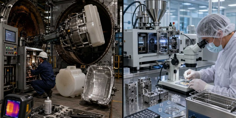
- Preventive maintenance plan for EBM and ISBM blow molding machines
Technical Guide to the Maintenance of Plastic Blow Molding Machines: Differences Between EBM and ISBM, Blow Heads, PWDS, Molds, Compressed Air, and IR Lamps
Author: Marco Arezio. Expert in circular economy, polymer recycling, and industrial plastics processing. Founder of the rMIX platform.
Publication date: March 25, 2026
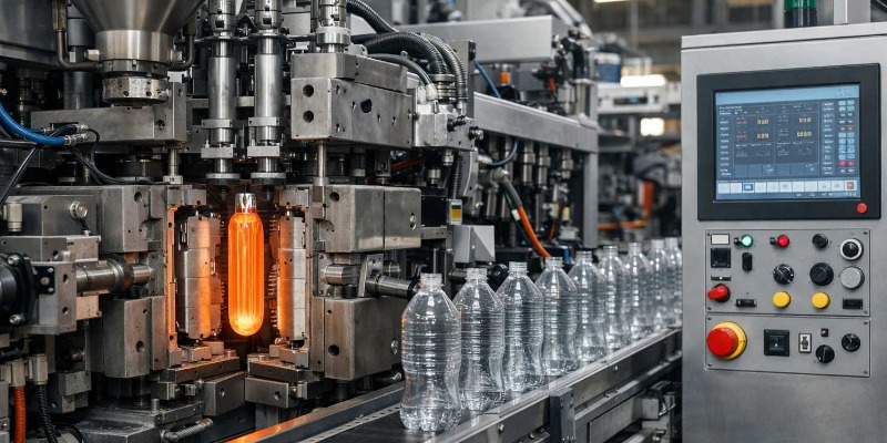
How Plastic Blow Molding Machines Work
Plastic blow molding is one of the most important processes in the industrial transformation of polymers intended for rigid packaging, technical containers, and a wide range of hollow articles. Bottles, vials, jerrycans, drums, tanks, ducts, and components for the automotive sector are produced through a manufacturing logic that appears simple but is, in reality, extremely sophisticated from a rheological, thermal, mechanical, and maintenance standpoint. At the core of the process is the controlled expansion of a polymer in the form of a preform or parison, by means of compressed air, inside a closed mold that defines the final geometry of the part.
The industrial relevance of this technology is enormous. The global rigid plastic packaging sector depends to a large extent on blow molding machines, especially for PET bottles used for beverages and for HDPE and PP containers used for detergents, personal care products, foods, and technical fluids. In Europe, the production of PET bottles made using ISBM technology alone amounts to tens of billions of units per year, while extrusion blow molding continues to dominate the market for bottles and containers in HDPE, PP, and multilayer structures.
This industrial centrality requires reflection not only on how the machine works, but also on its reliability. In a processing plant, in fact, the blow molding machine is not simply a forming machine: it is the point where material quality, mechanical precision, thermal control, compressed air management, mold stability, and inline quality control all converge. Even a modest degradation in just one of these subsystems can result in increased scrap, worsening wall thickness distribution, sealing defects, excessive raw material consumption, or unplanned downtime.
For this reason, a truly complete analysis of blow molding machines cannot be limited to describing the production cycle. It must include the architecture of the main technological families, the function of critical components, wear mechanisms, and maintenance strategies that preserve both container quality and line productivity.
Technical Differences Between EBM Blow Molding and ISBM Blow Molding
From an industrial standpoint, blow molding machines are divided into two major families: extrusion blow molding, indicated by the acronym EBM (Extrusion Blow Molding), and injection stretch blow molding, known as ISBM (Injection Stretch Blow Molding). These two families share the final principle of pneumatic expansion of the polymer inside a mold, but differ radically in architecture, processable materials, characteristics of the container produced, and maintenance criticalities.
In the EBM process, the plastic material is plasticized by an extruder and turned into a molten tube called a parison, which descends vertically from the blow head. When the parison reaches the desired length, the mold closes, pinches the material, seals it at the ends, and compressed air inflates it against the cold surfaces of the cavity. The process is relatively flexible, suitable for a wide variety of polymers, and especially competitive for containers in HDPE, PP, PVC, PA, PC, and coextruded multilayer structures. EBM dominates the production of bottles, jerrycans, small drums, and large tanks, covering volumes that can range from a few tens of milliliters to thousands of liters.
ISBM, by contrast, operates in two stages. In the first, an injection molding machine produces a preform with a finished neck; in the second, the preform is heated in an infrared oven and then stretched and blown in the final mold. This two-step process makes it possible to obtain biaxial orientation of the material, with remarkable advantages in terms of thickness distribution, transparency, mechanical properties, and gas barrier performance. For this reason, ISBM has become the reference process for PET in beverage packaging and for numerous applications in the cosmetics, food, and pharmaceutical sectors.
The different nature of the two processes also creates two distinct maintenance worlds. In EBM machines, maintenance revolves mainly around the blow head, the PWDS, the pinch-off areas, the blow pins, and the pinching system. In ISBM machines, on the other hand, the critical points are the IR oven, the lamps, the preform transport chain, the mandrels, the stretch rods, the high-pressure valves, and the stability of the mold cooling system. Understanding this distinction is essential, because an effective maintenance plan cannot be transferred mechanically from one technology to the other.
Continuous and Accumulator Blow Heads: Characteristics and Limits
In extrusion blow molding, the blow head is the heart of the machine. The quality of the parison, its concentricity, thickness distribution, and ultimately the strength and uniformity of the finished container all depend on it. EBM heads are mainly divided into two types: continuous-flow heads and accumulator heads.
The continuous-flow head feeds the parison uninterruptedly. The mold opens and closes while the extruder continues to push the molten material through the annular channel of the head. This configuration is ideal for small- and medium-volume containers, particularly in the range between 0.05 and 10 liters, with an optimal condition often below 5 liters. In these applications, productivity is extremely high: on multicavity machines for bottles of about 500 mL, it is possible to reach up to 40–60 cycles per minute, a figure that makes this architecture the dominant industrial choice for large volumes of detergent, cosmetic, and food bottles.
The materials most commonly used on continuous heads are HDPE, PP, PVC, and coextruded multilayer structures, while the components requiring the greatest maintenance attention are the mandrel, the outer ring, the concentricity adjustment system, the PWDS, the blowing nozzles, and the pinching system. In fact, even a minimal loss of concentricity in the annular channel can produce an eccentric parison, with irregular thickness distribution even before the inflation phase.
The accumulator head, on the other hand, meets the demands of large-volume production. Here, the plastic material is not delivered continuously but accumulated in a cylindrical chamber and then rapidly expelled by a piston. The reason for this solution lies in the behavior of the large-mass parison: if it were extruded slowly, it would collapse or deform under its own weight even before the mold closes. For this reason, accumulator systems are typically used for containers from 10 up to 2,000 liters, such as industrial drums, tanks, technical components, and large automotive parts.
From a productivity standpoint, accumulator heads operate at lower rates, normally between 1 and 6 cycles per minute, but require far greater precision in parison management. In these cases, high-resolution thickness control is not optional but necessary, because a local thickness error can compromise the mechanical strength of the entire container. The most common materials are HDPE, PP, PA, PC, and EVOH in coextrusion, while critical maintenance areas include the piston, the accumulator cylinder, the discharge valve, the PWDS system, and the blow ring.
In both configurations, the blow head must be regarded not only as a forming element, but as a precision system subject to pressure, temperature, abrasion, and contamination. Preventive maintenance and correct geometric calibration directly affect quality, container weight, and polymer consumption.
PWDS and Parison Thickness Control in EBM Blow Molding Machines
One of the most sophisticated and delicate systems in modern EBM machines is the Parison Wall Distribution System, often referred to by the acronym PWDS. Its function is fundamental: to modulate the thickness of the parison along its length in order to compensate for the future deformations the material will undergo during blowing. In other words, the system anticipates the points where the container will tend to thin and locally increases parison thickness before it is expanded in the mold.
Without this type of correction, a blow-molded container would inevitably have highly uneven walls. The areas furthest from the air entry point or subject to greater stretching would end up with reduced thickness and therefore lower mechanical performance. This means lower compression resistance, lower stiffness, poorer impact behavior, greater risk of deformation, and, in some cases, loss of tightness.
From a design standpoint, the PWDS acts by axially modifying the position of the mandrel relative to the head ring, thereby varying the cross-section of the annular channel and, consequently, the local flow of molten material. In modern heads, control can reach 32, 64, or even 128 points along the parison stroke, allowing for extremely fine adjustment. Such precision is particularly important in large containers, complex technical parts, and multilayer structures, where mass distribution must be controlled with the utmost care.
But it is precisely the complexity of the system that makes it a critical maintenance point. The PWDS includes hydraulic or electric actuators, linear position sensors, sliding guides, sealing systems, and mechanical parts that operate near a thermally severe environment. The most frequent issues are not necessarily obvious failures, but progressive drifts: small deviations between the commanded position and the actual position of the mandrel, synchronization errors, slow actuator response, and noise in the position transducers.
For this reason, PWDS calibration should never be considered an extraordinary activity. In plant conditions, a good practice is to verify the system every 500–1,000 operating hours, as well as after any mechanical intervention on the head or any major change in material and product. A PWDS that is out of calibration does not always generate a visible defect to the naked eye; very often it produces containers that appear correct but have non-optimal thickness, greater resin consumption, and reduced mechanical strength. It is precisely in these cases that the hidden cost of poor maintenance becomes more dangerous than an obvious machine stoppage.
EBM Clamping Systems and Molds: Critical Components and Maintenance
In EBM machines, the clamping system is responsible for opening and closing the mold, ensuring correct pinching of the parison, and withstanding the internal pressure developed during blowing. At first glance its function may seem similar to that of injection molding presses, but in reality the operating conditions are different: clamping forces are often lower, opening and closing speeds are much higher, and the overall kinematics can be more complex, especially in rotary or double-station machines.
The most common configurations for small and medium containers include clamshell systems, in which the two mold halves rotate laterally around a vertical hinge pin. This is a mechanically simple solution and very suitable for high operating frequencies, but precisely because of its speed it requires accurate control of the parallelism between the two halves. If this parallelism deteriorates, the pinch line worsens, parison sealing becomes less uniform, and flash, burrs, and the risk of leakage increase.
The components most exposed to wear in these systems are the hinge pins, bushings, actuation cylinders, and the locking mechanisms in the closed position. In rotary machines, on the other hand, maintenance becomes even more complex due to the presence of rotating distributors for air and water, rotary unions, multiple kinematic systems, and synchronization among the various stations in the cycle. In these lines, designed for high productivity on small-volume bottles, continuity of service depends directly on the reliability of the fluid supply systems to the rotating stations.
EBM molds deserve specific discussion. In most applications they are made of aluminum, thanks to its high thermal conductivity, which enables faster cooling and shorter cycles. In some cases, especially where there are conditions of strong abrasion or high internal pressures, steel is preferred, as it offers greater hardness and surface durability but less favorable cooling times.
The mold cooling system is one of the true keys to productivity. In EBM lines, cooling can account for as much as 60–75% of the total cycle time, and this means that any degradation of channels, heat exchange, or flow rate immediately translates into loss of productivity or premature extraction of the container, with post-mold deformation and dimensional instability. The cooling channels of aluminum molds are also vulnerable to the use of water that is not properly treated: scale deposits, galvanic corrosion between dissimilar metals, and damage to fittings can progressively compromise thermal performance.
For proper mold management, the maintenance plan must consider several levels of attention. The cavity surfaces must be cleaned at every production changeover and visually inspected at least quarterly. Guides and columns require regular lubrication, often every 100–500 hours depending on the installed system, along with annual play verification. Inserts and cores must be checked for fastening integrity at high frequency, for example every 50,000 cycles, and dimensionally verified at least once a year.
A machine that operates with well-cooled molds, stable guides, and correctly aligned clamping systems produces more consistent containers and drastically reduces the hidden industrial cost associated with poor quality.
Pinch-Off Areas, Mold Cooling, and Wear in Blow Molding Lines
Among all the design details of the EBM mold, the pinch-off areas are probably the most critical. It is in this zone that the two mold halves close around the parison, seal it, and separate it from the excess material. Every production cycle therefore subjects the pinch-off area to contact with still-hot material, mechanical impact, abrasion from the flash, and repeated thermal stresses. It is therefore no surprise that this is the fastest-wearing area of the entire mold.
The degradation of the pinch-off areas is not just an aesthetic issue. A change in their geometry causes worsening sealing quality, increased flash, burrs that are more difficult to remove, lower cutting precision, and, in more advanced cases, loss of container tightness. In practice, when the pinch-off wears down, the defect does not remain confined to the joining line: it propagates to the overall mechanical strength of the part.
For this reason, pinch-off areas must be included in a real preventive maintenance plan, not one based only on the appearance of visible defects. A profilometric inspection every 500,000–1,000,000 cycles is an industrially sensible threshold, while regrinding becomes advisable when wear depth exceeds 0.2 mm. Intervening on this element in a specialized workshop, through regrinding or localized build-up followed by machining, is almost always more economically advantageous than allowing the entire mold to degrade until replacement becomes necessary.
Alongside the pinch-off, cooling remains just as strategic. Cooling channels must be kept clean and intact, because even a modest reduction in flow rate or heat transfer coefficient affects the solidification time. Proper maintenance includes annual chemical cleaning, at least semiannual water analysis, and replacement of O-rings and fittings at scheduled intervals, often every two years. It is here that preventive maintenance ceases to be a cost and becomes a productivity factor: a clean channel reduces cycle time, stabilizes dimensional quality, and limits post-extraction deformation.
A maintenance manager who neglects the pinch-off and cooling systems tends to perceive only the final defects, but in reality is allowing two of the most important levers of blow molding machine efficiency to deteriorate.
Compressed Air, Blow Pins, and ISO 8573-1 Quality
The blowing system includes the generation of compressed air, its treatment, distribution to the stations, and its introduction into the parison or preform through pins, mandrels, and valves.
In many workshops, compressed air is considered a support utility, but in the reality of blow molding it is a true process variable. Its pressure, stability, oil content, particulate content, and moisture directly affect both the quality of the container and the service life of pneumatic components.In EBM machines, blowing pressure generally operates in the range of 4–12 bar for standard HDPE and PP containers, but can rise to 20–40 bar for technical materials, thin walls, or applications requiring high geometric definition. This means that it is not enough simply to have air available: it must be available with consistent quality. If the air contains aerosolized oil, solid residues, or excessive moisture, problems can appear as internal contamination of the container, poorer sealing, fouling of valves, accelerated wear of pneumatic elements, and nonconformities in sensitive applications.
In the food and pharmaceutical industries, compressed air quality must be consistent with the requirements of ISO 8573-1, which defines purity classes for oil, water, and particulates. In particular, for the most sensitive applications it is essential to keep oil at very low levels, in Class 1, therefore below 0.01 mg/m³, and to maintain the dew point at suitable values, typically below +3 °C in systems with refrigerated drying, or even lower if the process requires it.
Blow pins are precision components and deserve special attention. They penetrate the parison to introduce air and must do so with constant geometry, correct sealing, and precise synchronization. The tip of the pin wears progressively through contact with the hot material, tends to round off, and can generate less clean holes, increased flash, deterioration in the neck area, and instability in air distribution. Even clogging of the internal channel, especially after sudden stoppages without cleaning, is a frequent cause of intermittent defects.
For this reason, it is advisable not to wait for an obvious failure. A visual inspection of the tip every 500,000 cycles and preventive replacement every 3–6 million cycles for standard materials represent an industrially efficient strategy. With filled, abrasive, or reinforced materials, the frequencies may become significantly shorter.
As for compressors, their maintenance must not be improvised. In reciprocating compressors, oil changes often need to be carried out every 500–1,000 hours, air filters replaced every 500 hours, valves checked every 2,000 hours, and piston sealing rings replaced every 5,000–8,000 hours. In screw compressors, the intervals are longer, but oil changes, oil separators, filters, and minimum pressure checks remain critical. The dryer must be followed consistently through monthly dew point monitoring, condenser cleaning, and verification of proper condensate drainage.
Air receiver tanks also fall within a precise maintenance framework. In addition to daily condensate draining and periodic visual inspection, they must be managed in accordance with pressure equipment regulations, with updated records and timely scheduling of inspections. In a well-managed blow molding system, compressed air is not an ancillary service: it is an integral part of the quality system.
IR Ovens, Lamps, and Preform Transport Chains in ISBM Machines
In ISBM machines, the preform heating oven is one of the most delicate subsystems in the entire line. If the blow head is the heart of EBM, the IR oven is the truly critical organ of ISBM. The reason is simple: the entire success of stretch-blow molding depends on the preform reaching a very precise thermal window, with the correct temperature distribution both along the axis and through the thickness.
In the case of PET, the preform must reach the stretch station in conditions such that it can deform without rupture, collapse, whitening, or haze. In practical terms, the temperature range is often between 95 and 115 °C, but the absolute number matters less than uniformity and repeatability. A poorly heated preform does not merely generate a visual defect: it alters final thickness distribution and can compromise resistance, top load, gas barrier performance, and neck quality.
Quartz IR lamps are the main actuators of this thermal balance. They operate with a typical service life between 2,000 and 5,000 operating hours, but their actual life depends strongly on voltage fluctuations, the number of start-stop cycles, ambient conditions, and bulb cleanliness. Here an often underestimated aspect emerges: replacing only the failed lamp may seem convenient, but it creates a non-uniform set of emitters, with different radiation levels from one oven zone to another. For this reason, in the most demanding lines, preventive replacement of the entire set is the most rational practice.
The reflectors deserve the same attention. Even slight dulling or contamination of their surface reduces reflection efficiency, alters the thermal profile of the preform, and often forces operators into recipe compensations that mask the problem without solving it. Regular cleaning, visual checks, and scheduled replacements therefore become an integral part of heating quality.
The preform transport chain is another crucial point. The preforms are supported by the neck, rotate on themselves during their passage through the oven, and must maintain stable positioning. Wear in the pins, bushings, mandrels, and gearmotor causes pitch errors, instability in oven residence time, and non-uniform heating. A monthly check of chain elongation, which should not exceed values on the order of +0.5%, together with lubrication and mandrel inspection, makes it possible to prevent slow but highly penalizing drifts.
In ISBM, even more than in EBM, maintenance does not serve only to avoid downtime: it serves to preserve process repeatability. An IR oven that ages badly makes the entire line unstable.
Stretch Rods, Molds, and Quality Control in PET Blow Molding Machines
The stretch-blow station is the point at which the heated preform becomes a finished container. Here the combination of axial stretching, produced by the stretch rod, and radial deformation induced by high-pressure air takes place. The synchronization between these two events determines the success of the process: if the rod descends too early, too late, or with altered kinematics, thickness distribution becomes irregular and weak areas are generated, especially in the base and shoulder regions of the container.
Stretch rods are apparently simple elements, but their reliability is crucial. They must maintain straightness, surface integrity, correct tip geometry, and smooth sliding in the guides. A modest deformation, on the order of a few tenths of a millimeter, may be enough to create asymmetric stretching and therefore off-spec bottles. As an operating criterion, a maximum deflection on the order of 0.1 mm per meter already represents a useful threshold for deciding whether a rod should be reground or replaced.
ISBM molds, mostly made of polished aluminum, operate under tightly controlled thermal conditions. Cooling is essential for both productivity and the optical and dimensional quality of the container. In standard PET applications, mold temperature is normally maintained with chillers, and degradation of the cooling channels immediately produces longer cycles or less stable parts. Here too it is useful to regularly check flow rate and temperature difference between inlet and outlet, trying to keep ΔT within tight limits, for example around 2 °C in order to maintain uniform heat exchange.
Modern lines often integrate inline quality control systems that verify weight, height, neck diameter, thickness, and other critical parameters. These systems should not be regarded as simple inspection accessories, but as real sensors of process condition. When correctly calibrated, they make it possible to identify a drift before it turns into a nonconforming batch. When they are dirty, out of calibration, or neglected, they themselves become a source of error.
The calibration of these systems is particularly delicate. Even a very small shift in the instrument baseline can lead to rejection of good containers or, worse, acceptance of under-thickness parts. In a sector such as pressurized beverage packaging, this is not merely a yield issue: it is a product safety issue. Optics, sensors, certified reference samples, processing software, and periodic verification procedures must therefore be fully included in the plant maintenance plan.
Preventive Maintenance Plan for EBM and ISBM Blow Molding Machines
A truly effective maintenance plan for blow molding machines must be built around the logic of the process, not just around the calendar. In EBM and ISBM lines, critical components do not all degrade in the same way and do not all have the same impact on product quality. For this reason, combined maintenance is needed, made up of daily checks, cycle-based inspections, machine-hour verifications, and periodic activities based on actual plant data.
In the case of EBM, the blow head requires daily verification of annular channel concentricity, temperature, and nozzle cleanliness. The PWDS must be calibrated at a frequency on the order of 500–1,000 operating hours, checking the correlation between the command and the actual mandrel position. The pinch-off areas deserve profilometric inspection every 500,000 cycles, while blow pins can be included in a preventive replacement plan around 3 million cycles, depending on material and process severity. Mold cooling channels should be checked at least semiannually, verifying flow rate, fitting condition, cleanliness, and thermal drop.
In the case of ISBM, maintenance shifts to other nodes. IR lamps must be tracked with hour meters and replaced preventively, often every 2,000–3,000 hours in more conservative approaches, with reflector cleaning carried out at the same time. The preform transport chain requires monthly verification of elongation, lubrication, and mandrel inspection. Stretch rods must be checked periodically for straightness, tip condition, and sliding behavior. High-pressure valves and pressure switches must be included in a plan to verify the tightness and stability of the blowing circuit.
Common to both technologies is the need for rigorous maintenance of the compressed air system. Oil changes, filters, valves, dew point, oil content, and tank condition cannot be left to corrective maintenance alone. Spare parts management also takes on a strategic role: IR lamps, pins, seals, O-rings, position sensors, coalescing filters, and critical pneumatic components should be treated as essential technical stock, especially in plants running three shifts or with high service levels.
The maintenance maturity of a blow molding machine is not measured only by the number of failures. It is measured by the ability of the plant to maintain weight, thickness, dimensional stability, and productivity within tight ranges over long periods. It is in this continuity that true competitive advantage is created.
Overview of Blow Molding Machine Manufacturers and Maintenance Implications
The blow molding machine market shows a very clear specialization among manufacturers focused on PET beverage applications, producers focused on EBM, and companies with a strong presence in technical, pharmaceutical, or cosmetic segments. This segmentation is not merely commercial: it directly affects how line maintenance must be built.
In the ISBM segment for PET beverage, major international manufacturers have developed extremely high-productivity machines, with architectures pushed to the limit in terms of automation, energy recovery, and process control. In these lines, the strength lies not only in speed, but also in the quality of technical documentation, spare parts availability, and standardization of stretch-blow modules. For the maintenance manager, this means being able to work with advanced diagnostics, but also having to manage more sophisticated components, often heavily integrated at the software level.
In the EBM sector, historically stronger manufacturers stand out for mechanical robustness, head quality, coextrusion management, and the ability to process large volumes. In these machines, maintenance remains more “physical,” in the sense that success depends heavily on geometric precision, mold condition, cooling, guides, accumulator pistons, and the quality of mechanical adjustments.
For those managing production in Italy or in Europe, beyond machine specifications, the quality of local support and the speed of availability of lamps, mandrels, valve assemblies, position sensors, and compressed air system components matter greatly. An excellent blow molding machine from a technical standpoint can become penalizing if inserted into an ecosystem of slow or poorly supported spare parts. In an industry where the cost of line stoppage is often measured in thousands of lost pieces per hour, maintenance cannot be separated from the manufacturer’s support chain.
Conclusions
Blow molding machines, whether EBM or ISBM, cannot be fully understood if they are viewed only as forming equipment. They are complex systems in which polymer rheology, heat transfer, pneumatics, precision mechanics, automation, and quality control all converge. In each of these areas lie the factors that determine the success of the process or its drift.
In EBM lines, the technical domain belongs to the blow head, parison control, molds, and pinch-off areas. In ISBM lines, the heart of performance lies in the quality of the IR oven, the uniformity of preform heating, the synchronization of the stretch-blow station, and the stability of cooling. In both cases, maintenance is not an ancillary function but a structural component of quality.
The difference between a blow molding machine that produces and one that produces well, consistently, and with industrial margin lies precisely here: in the ability to translate data, inspections, frequencies, and weak signals into a coherent preventive plan. Where maintenance is only reactive, the process becomes more costly, more unstable, and less controllable. Where, instead, the machine is read as a system to be kept in balance, the result is more efficient, more reliable, and more sustainable production, also from the standpoint of raw material and energy use.
Technical FAQ on Blow Molding Machines
How often should the PWDS be calibrated in EBM blow molding machines?
Under normal industrial conditions, the PWDS system should be checked and calibrated every 500–1,000 operating hours, as well as after mechanical interventions on the head or significant product and material changes.
When is it advisable to replace the IR lamps of an ISBM blow molding machine?
Preventive replacement of the entire set is often preferable to replacing only the failed element. In many plants, the interval falls between 2,000 and 5,000 hours, depending on electrical stability, the number of start-ups, and the quality required.
Why are pinch-off areas so important in EBM molds?
Because they are the area where the parison is pinched, sealed, and separated. If they wear out, sealing, tightness, flash quality, and container strength all worsen.
What is the most underestimated parameter in the compressed air system?
Very often, air quality. Oil content, moisture, and particulates directly affect both container conformity and the service life of valves, pins, and pneumatic components.
What is the most important maintenance difference between EBM and ISBM?
In EBM, the main criticality is thermo-mechanical and concerns the head, the parison, and the molds; in ISBM, the most delicate point is the thermal control of the IR oven and the repeatability of the stretch-blow stage.
Sources
ISO 8573-1: compressed air, contaminants, and quality classes
Technical documentation and industrial manuals on extrusion blow molding and injection stretch blow molding
Regulations on pressure equipment and the management of compressed air receiver tanks
Technical maintenance manuals for compressors, dryers, coalescing filters, and pneumatic systems
Technical literature on blow molding processes for PET, HDPE, PP, and technical materials