


- How an Injection Molding Machine Works: Process Principle, Cycle Phases, and Critical Variables
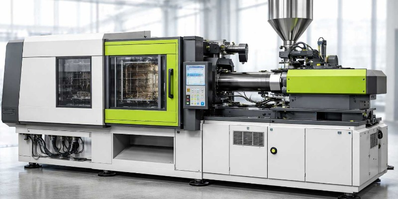
- Injection Units in Plastics Presses: Structure, Functions and Performance
- Plasticizing Screws: Geometry, Construction Materials and Wear Phenomena
- Plasticizing Cylinder: Tolerances, Radial Clearance and Maintenance Checks
- Nozzle, Screw Tip and Check Valve: Process Stability and Field Diagnostics
- Injection Molding Machine Clamping Group: Toggle, Direct System and Mechanical Criticalities
- Columns, Plates and Mold Parallelism: Geometric Precision and Operational Reliability
- Hydraulic Systems in Injection Molding Machines: Filtration, Oil Cleaning, and Failure Prevention
- Hydraulic, Hybrid, and Full-Electric Presses: Technical Differences and Maintenance Implications
- Cylinder and Mold Thermoregulation: Resistances, Chillers, Technical Water and Production Continuity
Technical guide to hydraulic, hybrid, and full-electric injection molding machines: operation, plastification unit, clamping unit, hydraulic systems, servo drives, temperature control, and industrial maintenance criteria
Author: Marco Arezio. Founder of the rMIX platform and author of technical content dedicated to plastic materials, industrial processes, circular economy, and the reliability of processing plants.
Publication date: March 19, 2026
Technical Abstract
The injection molding machine is one of the central machines in plastics processing. It is not merely a part production system, but a complex mechatronic platform in which plastification, pressure generation, mold closing, thermal control, electric drives, and digital logic must operate in a coordinated and repeatable manner. When even one of these subsystems deteriorates, the machine does not merely lose efficiency: it loses process stability, product quality, production availability, and maintenance reliability.
In the Italian context, the sector of machinery, equipment, and molds for plastics and rubber remains highly relevant from an industrial standpoint. According to Amaplast-MECS data, the sector closed 2024 with revenues exceeding €4.82 billion, exports amounting to €3.62 billion, and a structure made up of around 430 manufacturers and more than 15,000 employees. This figure does not measure the number of installed presses, but it does clearly describe the industrial weight of the supply chain to which injection molding belongs.
This first part of the article describes the machine according to a logic that is truly useful for maintenance personnel, process engineers, production managers, and plant technicians: not only “how an injection molding machine works,” but also which components are critical, how they deteriorate, which signals anticipate failure, and which checks must be included in a serious maintenance plan.
For references related to molded test specimens and machine-process consistency, the updated standard is ISO 294-3:2020, which replaced the now-withdrawn 2002 version. For monitoring particulate contamination in hydraulic fluids, the correct reference is ISO 4406:2021. For the digital integration of the press with MES and robots, the reference recommendations are EUROMAP 77 and EUROMAP 79, both based on OPC UA interfaces.
Technical Warning
Disassembly, measurement, realignment, calibration, seal verification, component replacement, and maintenance activities on injection molding machines must be performed exclusively by qualified personnel, following the OEM manual, LOTO procedures, and the applicable safety requirements. This applies in particular to the clamping unit, pressurized hydraulic circuits, band heaters, servo drives, screw-barrel assemblies, and molds.
1.1 — Operating Principle and Injection Cycle
The basic principle of injection molding is well known: the polymer is plastified inside the barrel, accumulated in front of the screw, injected into a closed mold, held under pressure to compensate for shrinkage, cooled to solidification, and finally ejected. In industrial practice, however, this linear scheme translates into a much more complex dynamic. Each phase imposes different mechanical, thermal, and fluid-dynamic loads on the machine, and it is precisely from this alternation of stresses that the main deterioration mechanisms arise.
A modern press must not only achieve a certain injected volume or a given clamping force. It must repeat thousands of cycles with minimal variations, keeping time, pressure, speed, temperature, screw position, clamping system response, and temperature-control conditions constant. The real reliability of the press depends on this repeatability.
1.1.1 — The Phases of the Injection Cycle
The plastification phase is the one in which the screw rotates, conveys the granules, and generates a homogeneous melt thanks to the combination of external heat supplied by the heaters and internal heat produced by mechanical work. It is the phase most sensitive to the condition of the screw, the barrel, and the non-return valve.
The mold closing phase brings the moving platen into contact and develops the force required to counteract the opening pressure generated by the polymer in the cavity. Here, parallelism, the integrity of the kinematic mechanisms, lubrication of the pins, or the sealing of the cylinders become critical, depending on the clamping technology.
The injection phase is the most severe for the plastification unit: the screw advances axially, the material passes through the nozzle and runners, and the machine must rapidly develop high pressures while maintaining the set profile.
The holding or packing phase compensates for the shrinkage of the material during cooling. If the non-return valve does not seal properly, the actual filling of the cavity worsens even in the absence of obvious alarms.
Finally, the cooling and ejection phase determines a large part of the total cycle time. In many cases it is the true production bottleneck, and it depends above all on the thermal efficiency of the mold and the quality of the cooling circuits.
1.2 — Injection Unit: Architecture and Critical Components
The injection unit is the functional heart of the press. It must transform solid granules into a homogeneous molten mass, meter its volume with precision, and transfer it into the mold under speed and pressure control. This dual function makes the plastification unit the point in the machine where the most aggressive combination of abrasive wear, chemical corrosion, thermal fatigue, and mechanical stress is concentrated.
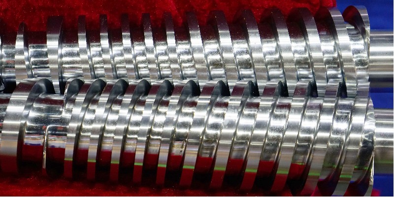
1.2.1 — The Plastification Screw: Geometry, Materials, and Wear
The plastification screw governs material conveying, compression, melting, mixing, and accumulation. Its geometry directly influences dosing stability, melt quality, thermal uniformity, and achievable pressure. In a standard three-zone screw, the feed section, compression section, and metering section are distinguished. Parameters such as nominal diameter, L/D ratio, compression ratio, channel depth, and flight profile determine compatibility with the processed material and wear resistance.
From a maintenance point of view, the key issue is not merely “how worn the screw is,” but where it wears and how this wear changes the behavior of the melt. Materials filled with glass fiber, hard mineral fillers, or particularly aggressive additives accelerate erosion of the flight and screw tip. Likewise, corrosive materials or inadequate cleaning intervals can compromise surfaces and sealing areas even in the absence of severe abrasion.
From a construction standpoint, the most common solutions range from nitrided steels to bimetallic or coated versions. The correct criterion is not to choose the “hardest” component in absolute terms, but the one consistent with the material mix, annual volumes, acceptable downtime, and total life-cycle cost.
Technical Note
Periodic measurement of the screw outside diameter in the areas most exposed to wear remains one of the most effective predictive maintenance activities. Its value increases further if it is correlated with machine hours, processed materials, and trends in part weight, cushion, and dosing time.
1.2.2 — The Plastification Barrel: Construction, Tolerances, and Deterioration
The barrel, coupled with the screw, constitutes the second fundamental element of the plastification system. It is not a simple container for the melt, but a precision component whose internal finish, surface resistance, and dimensional stability determine the efficiency of material conveying and compression.
In technical language, the most relevant parameter is the clearance between screw and barrel. When this clearance increases, plastification efficiency worsens: part of the material flows back, the ability to generate pressure effectively decreases, dosing times increase, and the machine tends to compensate with more aggressive adjustments that often worsen overall stability.
The dimensional tolerances referred to in the text must always be interpreted in light of the ISO system of limits and fits, of which ISO 286-1 and ISO 286-2 are the basic references.
Recommended Procedure for Measuring Clearance
The correct check is performed with the screw removed and cleaned, by measuring the screw outside diameter in the critical zones, measuring the barrel inside diameter with suitable instrumentation, and recording the results in the machine file. More than the single value, what matters is the wear curve over time, built using comparable data.
1.2.3 — Nozzle, Non-Return Valve, and Screw Tip
The nozzle connects the injection unit to the mold and must ensure flow continuity, thermal sealing, and compatibility with the material. An open nozzle reduces construction complexity but requires materials and conditions such as to limit drooling; a shut-off nozzle introduces an interception function useful for more critical materials, but increases the maintenance burden.
Even more delicate is the non-return valve, which opens during plastification to allow melt accumulation and during injection must close rapidly to prevent material backflow toward the screw. When this valve deteriorates, the machine may continue to operate apparently “well,” but the process gradually becomes less stable.
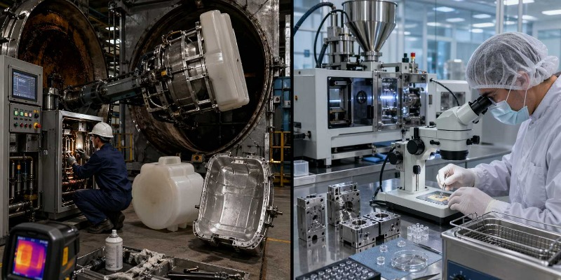
1.3 — Clamping Unit: Architecture, Systems, and Critical Components
The clamping unit has two functions: to open and close the mold with controlled speed and to keep the two mold halves clamped during injection. At the industrial level, the clamping unit is often identified with machine tonnage, but this simplification is reductive. What really matters is the ability to close precisely, maintain parallelism, distribute the load correctly, and preserve the mold over time.
1.3.1 — Toggle System
The toggle system remains widely used in medium-size presses thanks to its mechanical efficiency. The force applied by the actuator is amplified by an articulated kinematic mechanism, with advantages in terms of speed and reduced energy demand. From a maintenance perspective, however, this architecture requires constant attention to pins, bushings, articulation points, lubrication, and clearances.
When clearances increase, the defect does not manifest itself only as noise or loss of kinematic precision. The most serious consequence is the alteration of platen parallelism and force distribution on the mold, with an increased risk of flash, asymmetric wear, and damage to the mold itself.
1.3.2 — Direct Hydraulic System
In large-tonnage presses and in some specific applications, direct hydraulic clamping is preferred. In this case the kinematic arrangement is simpler, but precision depends even more on hydraulic circuit quality, cylinder sealing, valve stability, and oil contamination. Mechanical wear in articulated joints is reduced, but the importance of fluid-power maintenance increases.
1.3.3 — Tie Bars, Fixed and Moving Platens: Parallelism and Alignment
The tie bars guide the movement of the moving platen and transfer the loads of the clamping system. Their condition, together with platen flatness and parallelism, directly affects molding quality. Even small geometric differences can create uneven clamping force distribution, with visible effects on the part and invisible but more dangerous effects on the mold.
For precision applications and for test specimen production, the references of the ISO 294 family remain useful in emphasizing the need for a repeatable and geometrically consistent machine. The updated version for small plates is ISO 294-3:2020.
1.4 — Hydraulic Systems: The Energy Heart of the Press
In hydraulic and hybrid presses, the hydraulic system represents the main power transmission medium. Pump, tank, filters, valves, accumulators, cylinders, heat exchangers, and piping form an ecosystem in which fluid quality is as decisive as the quality of the components.
1.4.1 — Hydraulic System Architecture
Modern architectures favor variable-displacement pumps and servo-assisted logic to reduce consumption and dissipated heat. This improves energy efficiency, but makes fluid cleanliness control even more important. Precision pumps and valves in fact operate with extremely small internal clearances: uncontrolled contamination is enough to accelerate wear, internal leakage, and dynamic instability.
1.4.2 — Hydraulic Oil Quality Management
The international reference for classifying particulate contamination in oil is ISO 4406:2021, which defines the code used to express the number of solid particles present in the fluid. From a maintenance perspective, this means that oil control cannot be reduced to “clean or dirty oil”: formalized, comparable, and traceable monitoring over time is required.
Alongside solid contamination, the presence of water is one of the most dangerous factors.
It promotes oxidation, degradation of additives, corrosion, instability of the lubricating film, and abnormal valve behavior. A good maintenance program must therefore integrate particle analysis, water control, viscosity verification, filter inspection, and management of operating temperatures.1.5 — Control Systems and Electric Drives
The contemporary press is no longer just a mechanical or hydraulic machine. It is a digital machine. PLCs, HMIs, encoders, drives, sensors, industrial networks, and data acquisition systems are now an integral part of its reliability.
1.5.1 — Full-Electric, Hydraulic, and Hybrid Presses: Maintenance Implications
Full-electric presses eliminate much of the criticality related to hydraulic oil, improve precision and cleanliness, and reduce consumption in many applications. In return, they shift the center of maintenance toward servo drives, gear reducers, ball screws, encoders, electronic cooling, and drive obsolescence.
Hydraulic presses retain robustness, versatility, and widespread industrial use, but require strict discipline in oil quality and circuit maintenance.
Hybrid presses seek to combine the advantages of both: lower consumption, good dynamics, and good available force. However, precisely because they combine different technologies, they require broader skills and more cross-functional maintenance management.
1.5.2 — Servo Drives: Encoders, Motors, Drives
Brushless motors, absolute encoders, inverters, and power modules must be considered components subject to aging, not “maintenance-free” elements. Bearings degrade, encoders suffer from contamination and vibration, and drive capacitors age thermally. A mature maintenance plan must provide for parameter backup, control cabinet ventilation checks, thermal monitoring, and management of electronic obsolescence.
In terms of connectivity, the OPC UA standardization promoted by EUROMAP is increasingly valuable. EUROMAP 77 defines data exchange between press and MES; EUROMAP 79 governs the interface between press and robot; EUROMAP 83 provides the shared general definitions of the sector’s OPC UA interfaces.
1.6 — Temperature Control Systems: Heating and Cooling
Thermal control is one of the least spectacular yet most decisive pillars of injection molding. Without stable temperature control there is no repeatable process. The barrel must melt and maintain the polymer within the correct temperature range; the mold must remove heat as uniformly and quickly as possible.
1.6.1 — Band Heaters and Barrel Heating Systems
Band heaters divide the barrel into controlled thermal zones. Their deterioration does not always manifest itself as a complete failure. More often it appears as a progressive loss of efficiency, longer heating times, thermal oscillations, and persistent deviations between set-point and actual temperature. For this reason, maintenance should not be limited to “run-to-failure” replacement, but should include electrical checks, leakage verification, and comparison between absorbed power and thermal response.
1.6.2 — Mold Temperature Control: Chillers, Temperature Controllers, and Circuits
Mold cooling is not an accessory service: in many processes it is the factor that determines the actual cycle time. Clogged circuits, limescale deposits, galvanic corrosion, untreated technical water, leaks at fittings, and degraded heat exchange lead to warpage, dimensional instability, and increased cycle times.
From an industrial standpoint, technical water management should be treated as a process discipline: water quality, hardness, inhibitors, biological control, and scheduled circuit cleaning.
1.7 — The Injection Molding Machine Market and the Maintenance Implications of the Manufacturer
Knowing the market is not useful only for choosing which machine to buy. It also serves to understand how sustainable maintenance will be over the years. A press with good mechanical architecture but poor spare parts availability, incomplete documentation, unsupported drives, or an insufficient service network can quickly become an economic problem.
In the Italian market, European, Asian, and Japanese manufacturers coexist, with different specializations by tonnage, precision, packaging, automotive, medical, or large parts. More than chasing generic rankings, the technical manager should evaluate four elements: quality of the service network, spare parts availability, software/electronics structure, and documentation transparency.
Technical Conclusion of Chapter 1
Understanding the architecture of an injection molding machine means going beyond the simplified view of the machine as “tonnage + screw + mold.” In reality, the press is an integrated system in which every deterioration, even minimal, can be amplified through the process: a worn screw alters plastification, a non-return valve compromises packing pressure, a dirty hydraulic circuit destabilizes movements, an out-of-tolerance electric axis alters positions, and a scaled cooling circuit lengthens the cycle and worsens the part.
For this reason, press maintenance must not be conceived as an accessory or reactive activity, but as a technical function with direct impact on quality, productivity, consumption, mold life, and industrial profitability. The next part of this work should address measurement methods, inspection frequencies, machine record sheets, inspection protocols, and operating thresholds, transforming architectural knowledge into a real maintenance program.
Sources
The first fundamental reference is UNI EN ISO 20430:2020, the standard that defines the safety requirements for injection molding machines for plastics and rubber. It is now the most important reference for anyone describing the architecture, use, and safe maintenance of a press, also because it has replaced the older references previously used in the sector. At the level of European legislative framework, it is also essential to refer to Regulation (EU) 2023/1230 on machinery, which constitutes the new general regulatory framework for the safety of industrial machines and includes among the relevant machines those for injection or compression molding of plastics and rubber.
As regards process precision and technical consistency in the molding of test specimens, a useful and updated source is ISO 294-3:2020, dedicated to the injection molding of thermoplastic test specimens. Although it is not a standard centered on press maintenance, it is very useful when addressing repeatability, machine stability, and performance in precision applications. On the hydraulic systems side, the standard to cite is ISO 4406:2021, which defines the method for classifying the level of particulate contamination in fluids. It is the most solid basis for addressing the issue of hydraulic oil cleanliness, which in a traditional or hybrid press has a direct impact on pumps, valves, cylinders, and continuity of service.
When the article refers to concepts such as H7 tolerances, dimensional clearances, fits, or the precision of internal machining in the barrel and other mechanical components, the correct reference is the ISO tolerance system defined by ISO 286-1:2010 and ISO 286-2:2010. These standards help provide technical grounding for references to geometric tolerances and mechanical fits, avoiding wording that is too generic or not verifiable.
For the part relating to digital integration of the press, process data collection, connection with MES systems, and robot interfacing, the most appropriate sources are the EUROMAP 77 and EUROMAP 79 recommendations. The former concerns the interface between the injection molding machine and the Manufacturing Execution System; the latter the interface between press and robot. Both are now particularly important for placing the article in a modern perspective, consistent with the logic of interoperability, monitoring, and connected industry.
Finally, to contextualize the economic and industrial weight of the Italian plastics and rubber machinery sector, it is useful to cite the official data released by Amaplast-MECS. These documents make it possible to place the injection molding machine within a structured industrial supply chain, avoiding undocumented claims about the number of installed machines and instead keeping the discussion anchored to official data on revenue, exports, and sector size.
FAQ
What is an injection molding machine?
An injection molding machine is an industrial machine that melts a polymer material, pushes it under high pressure into a closed mold, and controls filling, holding, cooling, and ejection. It is one of the core technologies in plastics processing because it makes it possible to produce components with high repeatability, complex geometries, and high-productivity cycles.
What are the most important components of an injection molding machine?
The most critical components are the plastification unit, composed in particular of the screw, barrel, screw tip, and non-return valve, the mold clamping unit, the hydraulic or electric drive systems, the electronic control, and the temperature-control system. Each of these subsystems directly affects part quality, process stability, and machine availability.
Why is the plastification screw considered a critical component?
The screw is the component that conveys, compresses, melts, and mixes the polymer. Any alteration of its geometry due to wear, corrosion, or abrasion compromises melt quality and dosing consistency. This means that a degraded screw does not merely cause a mechanical problem, but also generates process instability, variations in part weight, and reduced production repeatability.
How can a worn non-return valve be recognized?
In production practice, the most common signs are cushion instability, variability in part weight, the need to increase packing pressure or holding time, and a general deterioration in cycle regularity. Often the deterioration of the valve does not generate an immediate direct alarm, but appears as a progressive drift in quality.
What is the difference between a hydraulic, full-electric, and hybrid press?
A hydraulic press uses hydraulic circuits to generate the main movements; a full-electric press uses electric servo drives; a hybrid combines the two technologies. Full-electric machines generally offer greater precision and cleaner operation, while hydraulic machines remain very widespread for their robustness and versatility. Hybrids seek a balance between dynamic performance, energy efficiency, and available force.
Why is hydraulic oil so important in a traditional press?
Because in a hydraulic press oil is not just a service fluid, but the medium through which energy is transmitted. If it is contaminated by particles or water, the degradation affects pumps, valves, cylinders, and the response precision of the machine. Poor oil quality management increases the risk of failures, performance drift, and machine downtime.
What is the main safety standard for injection molding machines?
The most important technical safety reference is UNI EN ISO 20430:2020, while the general European regulatory framework is given by Regulation (EU) 2023/1230 on machinery.
What are ISO 286 standards used for in an article about injection molding machines?
They serve to provide technical grounding for references to dimensional tolerances and mechanical fits. When discussing diameters, seats, screw-barrel clearances, or precision machining, it is correct to refer to the ISO system of limits and fits defined by ISO 286-1 and ISO 286-2.
Why does mold temperature control affect the cycle so much?
Because cooling quality directly influences cycle time, surface finish, deformation, and residual stresses in the part. Even a perfectly efficient machine can lose productivity and quality if the mold does not exchange heat uniformly and consistently.
What is the role of EUROMAP 77 and EUROMAP 79?
EUROMAP 77 defines the interface between the press and MES systems for process data exchange, while EUROMAP 79 concerns the interface between the press and the robot. They are fundamental references when discussing automation, data collection, interoperability, and digital integration in an Industry 4.0 framework.
Why does the press manufacturer also matter from a maintenance standpoint?
Because it is not enough to evaluate tonnage, speed, or purchase price. Spare parts availability, the quality of technical documentation, the service network, software support, and management of electronic obsolescence directly affect downtime costs, preventive maintenance, and the actual useful life of the machine.
How important is the Italian plastics and rubber machinery sector?
It is a highly significant industrial sector. Amaplast-MECS data show a sector with billions of euros in revenue and a strong export orientation, confirming the economic and technological importance of the machinery supply chain for plastics processing in Italy.